Convert Pipeline#
The Convert pipeline converts the raw Bayer image data into a BitmapImage, after moving through the pipeline.
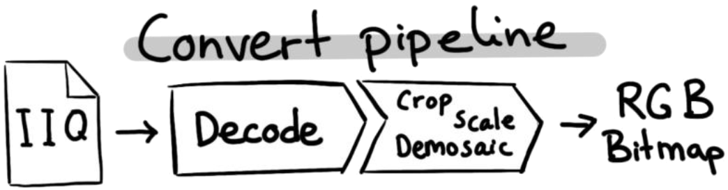
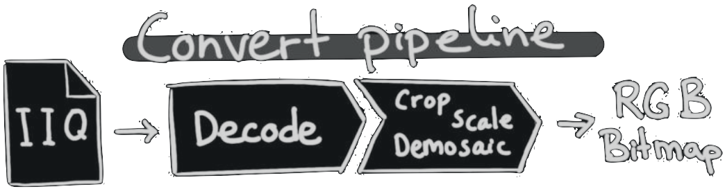
As the first step in the pipeline, the ImageSDK decodes the image, similar to the Decode pipeline (see Decode Pipeline).
Sensor Profiles#
When converting the raw Bayer data into RGB, ImageSDK applies what we call Sensor Profiles. A sensor profile is a generic image sensor characteristic. Each IIQ file defines what camera it originated from, and what sensor was in that camera. This information is now used, to correct for nonlinearity in the sensor output data. This means the resulting RGB image data will better reflect the sensors true dynamic range.
ImageSDK comes with a collection of “Sensor Profile”-files, that each define the sensor characteristics for sensors used in Phase One’s cameras. Since these are distributed as stand-alone files, ImageSDK must be aware of where to look for them on the file system. By default, it will look for the files in a folder called SensorProfiles in the current working directory, but you can specify the location manually.
Set the directory where ImageSDK looks for Sensor Profiles, using this global SDK method:
P1::ImageSdk::SetSensorProfilesLocation("path/to/SensorProfiles");
Sdk.SetSensorProfilesLocation(SENSOR_PATH);
Caution
For the SetSensorProfilesLocation method to have any effect, you must call it before you open any RawImage objects. The opening will fail with an error “Unsupported sensor” in case the SDK doesn’t find the appropriate sensor profile.
Ordering#
You cannot change the order of the steps in the convert pipeline. The order of the methods in the code itself is unimportant, as the Convert pipeline always will follow its own sequence of execution. This is due to performance optimization of the pipeline.
In the following example, we place the “scale”-step before the “crop”-step in the code:
config.SetOutputWidth(1024);
config.SetCrop(1000, 2000, 2048, 768);
config.SetOutputWidth(1024);
config.SetCrop(x: 1000, y: 2000, width: 1024, height: 768);
Despite the order of the process-steps in the code, the pipeline will still execute in a pre-determined order. I.e., the following example will yield the same result as the previous example:
config.SetCrop(1000, 2000, 2048, 768);
config.SetOutputWidth(1024);
config.SetCrop(x: 1000, y: 2000, width: 1024, height: 768);
config.SetOutputWidth(1024);
The output images from the two sample code snippets, will be identical.
The Configuration Object#
To use the Convert pipeline, you first create an empty ConvertConfig configuration object:
P1::ImageSdk::ConvertConfig config;
ConvertConfig config = new ConvertConfig();
After creating the object, you can apply a list of adjustments to the image.
Image adjustments#
To produce a desired output image, the recorded raw data can be tuned. A list of different adjustments help to render the output in a desired way. See the ConvertConfig documentation for the full set of adjustments.
The pipeline specify working range for those adjustments. If the user tries to set an adjustment outside of its boundaries, the setting will be clamped to the maximum/minimum value.
Noise Reduction#
The captured raw data inherently contains noise. To reduce it to a desired level an advanced noise reduction algorithm is used in the ImageSDK. The algorithm is based on a few user input parameters, which determine the quality of the noise reducion but too extreme settings may wash out details, making the image softer. Adequate values should be determined by the end user.
The recommended settings is mid-range (close to 0.5) for the LuminanceNoiseReductionAmount and the ChromaticNoiseReductionAmount, and enable the SinglePixelNoiseReduction only for images shot with ISO 3200 and above.
config.SetLuminanceNoiseReductionAmount(0.6);
config.SetColorNoiseReductionAmount(0.4);
config.SetNoiseReductionSinglePixelEnabled(true);
config.SetLuminanceNoiseReductionAmount(0.6);
config.SetColorNoiseReductionAmount(0.4);
config.SetNoiseReductionSinglePixelEnabled(true);
Note
Noise reduction algorithm is not run below 0.5 scaled output to reduce performance penalty for significantly small change.
Sharpening#
To ensure that the accutance of the output image is satisfactory, the ImageSDK pipeline includes a sharpening operation. The input parameters define the amount of restored details, but they may also introduce additional image noise or other artefacts, so it is recommended to find the appropriate settings for any given task. The SetSharpening method requires four parameters:
* amount controls the strength of the algorithm
* radius determines the area used to improve sharpness on any given pixel
* threshold forbids sharpening of weak features, which could be noise. This parameters is normalized, and 1.0 means the estimated noise level.
* haloSuppressionAmount will determine the strength of the supplementary algorithm to eliminate halo introduced by sharpening around high contrast edges
double sharpeningAmount = 1.87;
double sharpeningRadius = 1.0;
double sharpeningThreshold = 1.0;
double haloSuppressionAmpount = 0.0;

config.SetSharpening(sharpeningAmount, sharpeningRadius, sharpeningThreshold, haloSuppressionAmpount);
System.Double sharpeningAmount = 1.87;
System.Double sharpeningRadius = 1.0;
System.Double sharpeningThreshold = 1.0;
System.Double haloSuppressionAmpount = 0.0;

config.SetSharpening(sharpeningAmount, sharpeningRadius, sharpeningThreshold, haloSuppressionAmpount);
Highlight and shadow recovery#
The dynamic range of an image can be modified by increasing the shadows and reducing the highlights.
config.SetShadowRecovery(0.5f);
config.SetHighlightRecovery(0.5f);
config.SetShadowRecovery(0.5f);
config.SetHighlightRecovery(0.5f);
Coordinate systems#
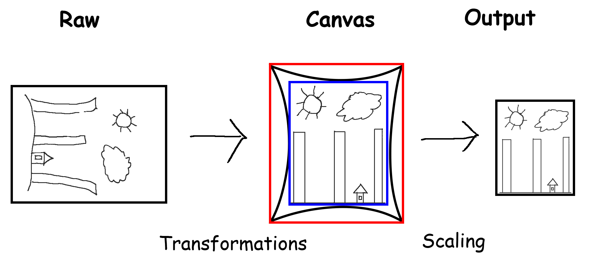
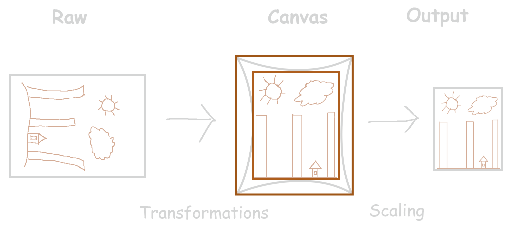
The image goes through a couple of geometric transformation in the conversion pipeline, and to be able to refer to certain coordinates on the image, it is important to define these transformations and related coordinate systems.
When the RawImage is loaded, the pixels are loaded into the Raw coordinate system.
Following that all transformations are applied, including geometric correction and orientation. After this the image is the Canvas coordinate system.
Because of some of the transformations, the image edges may become crooked, the transformed data will not be upright rectangle shaped (see black frame below). Still the image must be an upright rectangle.
There are multiple ways of handling this. By default the output image will be centered around the optical center, and will have the same size as the sensor dimensions. Alternatively the ImageSDK can output by using the external or internal bounding box as image data. This is illustrated by the red and the blue frames. See CanvasClip for available options.
Finally the image is scaled to the requested output size. Then the image is in Output coordinate system.
The origin in all coordinate system is at the top left corner.
Note
Some of these transformation may be identity transform, depending on the ConvertConfig and the RawImage.
Cropping#
You can request the pipeline to output a smaller portion of the image defined by a rectangle. This rectangle is defined by its top left corner and width and height in the canvas coordinate system.
Here is an example of how we apply “crop”:
config.SetCrop(1000, 2000, 1024, 768);
config.SetCrop(X: 1000, Y: 2000, width: 1024, height: 768);
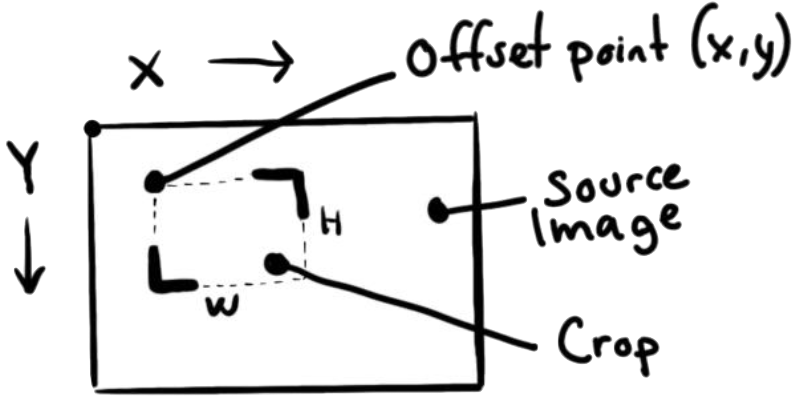
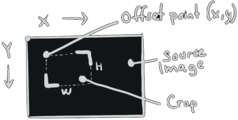
The crop will be placed on the source image as defined by the X and Y coordinates: the offset-point is the top-left corner of the cropped image (a positive Y-value is downwards). The width and height then defines the size of the cropped area (see Basic Image Info on extracting the width and height of the image).
Note
An attempt to crop the image outside the range of its own width and height (invalid values) throws an exception.
As the ImageSDK is optimized for performance, the crop size can potentially add a few pixels to the width and height. The width and height of the cropped output image may thus differ a few pixels from the given parameters.
Warning
This means you will very likely not get the exact crop offset or dimension you requested. Most likely it will be a few pixels off.
Scaling#
You can apply scaling of an image three different ways. SetOutputScale
Output Scale multiplies the size of the image by the input value
Output Image Width to a given number of pixels
Output Image Height to a given number of pixels
Those settings are mutually exclusive, so settings any of them will eliminate the previous setting.
If none of them are set the output image size will be 100% of the canvas size (see Cropping for details).
config.SetOutputScale(0.5);
config.SetOutputScale(0.5);
Undistorting#
Any optical system deviates from rectilinear projection in certain degree. If the output image requires photogrammetric precision, this inherent flaw must be mitigated by undistorting the captured image with a calibration dataset. ImageSDK contains the Distortion Correction operation to produce undistorted output.
To enable the Geometric Correction operation a flag needs to be set before the conversion is applied.
config.SetGeometricCorrectionEnabled(true);
config.SetGeometricCorrectionEnabled(true);
The SDK provides several methods for undistorting images, offering varying levels of precision and computational cost. It is up to the user to determine the best trade-off based on their specific needs. To select the desired method, one needs to set the GeometricCorrectionMethod to the appropriate value. The default value is Precise which runs the same method the previous operation
config.SetGeometricCorrectionMethod(GeometricCorrectionMethod::Approximated);
config.SetGeometricCorrectionMethod(GeometricCorrectionMethod.Approximated);
Phase One delivers all metric cameras with the calibration dataset in Australis format used by this function, but the end users may create their own calibration dataset.
For the Precise and Approximated methods the operation must be able to obtain the correct calibration data. The multihead cameras (PAS 280 and the nadir component of the PAS880 system) include this dataset, so undistort their images requires only this step.
For the rest of the cameras the user needs to provide this data as part of the ConvertConfig structure.
P1::ImageSdk::GeometricCorrection geometricCorrectionData;

geometricCorrectionData.focalLength = 145.49; // C [mm]
geometricCorrectionData.pixelSize = 0.00376; // H [mm]

geometricCorrectionData.k1 = -1.34e-5;
geometricCorrectionData.k2 = 3.1e-8;
geometricCorrectionData.k3 = 8.31e-12;

geometricCorrectionData.p1 = 1.22e-6;
geometricCorrectionData.p2 = -4.64e-9;

geometricCorrectionData.b1 = 1.46e-5;
geometricCorrectionData.b2 = -4.34e-9;

geometricCorrectionData.orientation = 90;

config.SetGeometricCorrection(geometricCorrectionData);
P1.ImageSdk.GeometricCorrection geometricCorrectionData = new GeometricCorrection();

geometricCorrectionData.c = 145.49;
geometricCorrectionData.h = 0.00376;

geometricCorrectionData.k1 = -1.34e-5;
geometricCorrectionData.k2 = 3.1e-8;
geometricCorrectionData.k3 = 8.31e-12;

geometricCorrectionData.p1 = 1.22e-6;
geometricCorrectionData.p2 = -4.64e-9;

geometricCorrectionData.b1 = 1.46e-5;
geometricCorrectionData.b2 = -4.34e-9;

geometricCorrectionData.orientation = 90;

config.SetGeometricCorrection(geometricCorrectionData);
On the other hand the Simplified method does not require such calibration data as it is based on the built in lens model based generic profile.
Warning
If Geometric Correction operation is enabled, but ImageSDK is unable to obtain valid calibration data required for the selected method, an exception is going to be thrown and the conversion will fail.
Please note the orientation property. As the correction is not radially symmetric, it is important to know which orientation the camera was set when the calibration data was generated so it can be applied correctly. The calibration data provided by Phase One is made in 0 degree orientation, but in-flight calibration might occur in different orientation.
As the australis format does not contain this information, it must be noted down by the user.
Note
Performance consideration: For the calibration data is constant for the full set of images taken with any camera during the flight, the Precise undistort method introduces a caching mechanism, which makes sure that the conversion is as fast as possible for multiple conversions. As this requires large amount of memory, only one calibration can be cached at a time.
Because of that it is recommended to queue the conversion operations such way that images from the same camera are converted sequentially to obtain optimal execution time when that method is being used. The other methods don’t use any caching mechanism, and produce the output with much smaller memory footprint.
Output format#
The default output of the converting pipeline is three channels (red, green, and blue), and 8-bit bit depth (0 to 255). One can request a custom format, which is defined by bit depth (8, 12 or 16 bits) and channel type (red, green, blue, luminosity, etc.).
// using predefined format
config.SetOutputFormat(BitmapFormat::Rgb48);
// or custom format
config.SetOutputFormat(BitmapFormat(BitDepth::U16, PixelLayout::Interleaved, {PixelComponent::Red, PixelComponent::Alpha, PixelComponent::Grey}));
// using predefined format
config.SetOutputFormat(BitmapFormat.Rgb48);
// or custom format
config.SetOutputFormat(new BitmapFormat(BitDepth.U16, PixelLayout.Interleaved, PixelComponent.Red, PixelComponent.Alpha, PixelComponent.Grey));
Applying conversion#
The final step is to process an image through the Convert pipeline. You do this with the ApplyTo method, as follows:
P1::ImageSdk::BitmapImage bitmap = config.ApplyTo(image);
BitmapImage bitmap = config.ApplyTo(image);
When you apply the Convert pipeline to an image, the image conversion (“Demosaic”) is also applied, converting the image from raw Bayer data into a BitmapImage. BitmapImage is an in-memory representation of the RGB bitmap data (the “viewable” image).
From here, you can choose to employ methods of your choice (based on the Host system) to e.g. save the image into the desired image container format (Tiff, Png, Jpg etc.).
It is important to note that the data contained in BitmapImage is not an image file, like a BMP file. Despite the naming overlap. If you write the content of BitmapImage to disk (say, with fwrite), it will not be in any image file format. It will just be a plain data file with RGB pixel data.
Obtaining Histogram data#
The ImageSDK can calculate the tonal distribution of the image for the stages of the conversion pipeline. They can be used for visual or evaluation purposes. It is possible to acquire those histogram using the following steps:
Define a list of stages you want to obtain the histograms
Convert the image with the actual
ConvertConfigRead the histogram from the acquired stages
P1::ImageSdk::RawImage image("test_input.iiq"); // Load the raw file
P1::ImageSdk::Histogram rawHistogram;

image.GetRawHistogram(&histogram); // The raw histogram can be obtained immediately

image.RequestHistogram(P1::ImageSdk::beforeLevels); // To show as an overlay on a Levels adjustment tool

image.RequestHistogram(P1::ImageSdk::beforeCurves); // To show as an overlay on a Curves adjustment tool

image.RemoveHistogram(P1::ImageSdk::beforeCurves); // This way a histogram request can be canceled before the conversion

P1::ImageSdk::ConvertConfig config;

P1::ImageSdk::BitmapImage bitmap = config.ApplyTo(image); // The image might be possible to use

P1::ImageSdk::Histogram levelsHistogram;

if (image.GetHistogramStage(&levelsHistogram, P1::ImageSdk::beforeLevels))
{

	P1::ImageSdk::HistogramType histogramType = levelsHistogram.GetType();

	int numChannel = levelsHistogram.GetNumChannel();
	int binSize = levelsHistogram.GetBinSize();


	for (int c = 0; c < numChannel; c++)
	{
		const int *histogramChannelData = levelsHistogram.GetChannel(c);

		for (int n = 0; n < binSize; n++)
		{
			// do something with the nth bucket
		}
	}
}

// this condition will fail as the RemoveHistogram() call removed this type of histogram
if (image.GetHistogramStage(&levelsHistogram, P1::ImageSdk::beforeCurves))
{
}
RawImage image = new RawImage("test_input.iiq"); // Load the raw file

Histogram rawHistogram = image.GetRawHistogram(); // The raw histogram can be obtained immediately

image.RequestHistogram(beforeLevels); // To show as an overlay on a Levels adjustment tool

image.RequestHistogram(beforeCurves); // To show as an overlay on a Curves adjustment tool

image.RemoveHistogram(beforeCurves); // This way a histogram request can be canceled before the conversion

ConvertConfig config = new ConvertConfig();

BitmapImage bitmap = config.ApplyTo(image); // The image might be possible to use

Histogram levelsHistogram;

if (image.GetHistogramStage(levelsHistogram, beforeLevels))
{
    HistogramType histogramType = levelsHistogram.Type;

    int numChannel = levelsHistogram.NumChannel;
    int binSize = levelsHistogram.BinSize;


    for (int c = 0; c < numChannel; c++)
    {
        const int *histogramChannelData = levelsHistogram.GetDataChannel(c);

        for (int n = 0; n < binSize; n++)
        {
            // do something with the nth bucket
        }
    }

}

Histogram curvesHistogram;

// this condition will fail as the RemoveHistogram() call removed this type of histogram
if (image.GetHistogramStage(out curvesHistogram, beforeCurves))
{
}
Note
The histogram will be calculated based on the ConvertConfig including the crop settings.